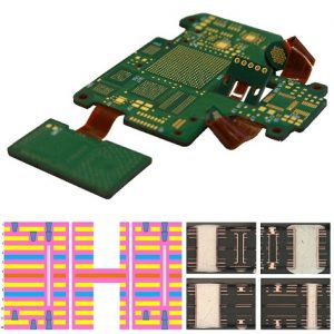
Material Selection Impacts Rigid-Flex PCB Fabrication
Rigid-flex circuits are increasingly popular for consumer electronics, ranging from laptops to smartphones and tablets. They are also used in medical devices such as hearing aids and pacemakers and for automotive electronic devices such as engine control units and navigation systems. In order to make rigid-flex PCBs, it is necessary to understand how the material choice of the substrate impacts the overall manufacturing process. Rigid-flex circuits are subject to a variety of environmental conditions, including temperature cycling and vibration. The quality of these circuits depends on the stability of both the flexible and rigid sections of the board, and the integrity of the transition between them. In addition, signal integrity and electromagnetic interference (EMI) must be maintained across the flex regions.
Several factors can impact the fabrication of rigid flex pcb fabrication, including the choice of the base material, copper thickness, and trace width/spacing. The thickness of the base material is a major factor in the cost of the board, as higher thicknesses lead to a greater stiffness and rigidity. However, too thin a thickness can result in the boards bending or cracking. The thickness of the conductive copper is another important factor, as thinner traces can be less durable and more susceptible to failure than thicker ones.

The material choice of the flex layers also has an impact on the final cost of the board. A common option for flex layers is FR-4, which provides a high-performance and low-cost solution. Other options for flex layers include a vapor deposition (VDI) copper film or an electrically-conductive polyimide (EIP).
How Substrate Material Selection Impacts Rigid-Flex PCB Fabrication
It is important to select a rigid-flex circuit material that will hold up to a wide range of temperatures and other conditions. It should also be able to withstand the stresses of thermal cycling and vibration. It is also critical to ensure that the flex and rigid portions of the board have similar thermal expansion coefficients. This can help to prevent metallurgical changes that could reduce durability and reliability.
When designing a rigid-flex PCB, it is essential to minimize the number of plated through holes and solder lands on the flex section. This can decrease assembly time and the cost of the PCB. It is also recommended that the flex reference planes be etched with a hatched pattern rather than solid to improve flexibility. This can help to avoid the stress on plated through hole vias caused by repeated bending of the circuit board.
A cover lay is applied to the top and bottom of a flex circuit to protect it from harsh environments, chemicals, and solvents. It is typically a FR-4 or polyimide film with an adhesive layer. Some manufacturers also use a soluble or thermosetting epoxy as an alternative to adhesives, which eliminate the need for cleaning and can withstand higher reflow temperatures. This allows for higher manufacturing speeds and reduced manufacturing costs. This layer also protects against EMI from outside sources, as well as from the effects of mechanical stress.